Writing an emulator: sound is still complicated
That last article was somewhat heavy, and I need a break1, so it’s perfect time to go back to our emulator.
If I took such a convoluted approach to explaining sound, it was with the hope that it would make today’s code easier to get into.
Back to sources
You should know the drill by now. Ultimate Game Boy Talk. Pan Docs. Chop chop!
Sound Overview
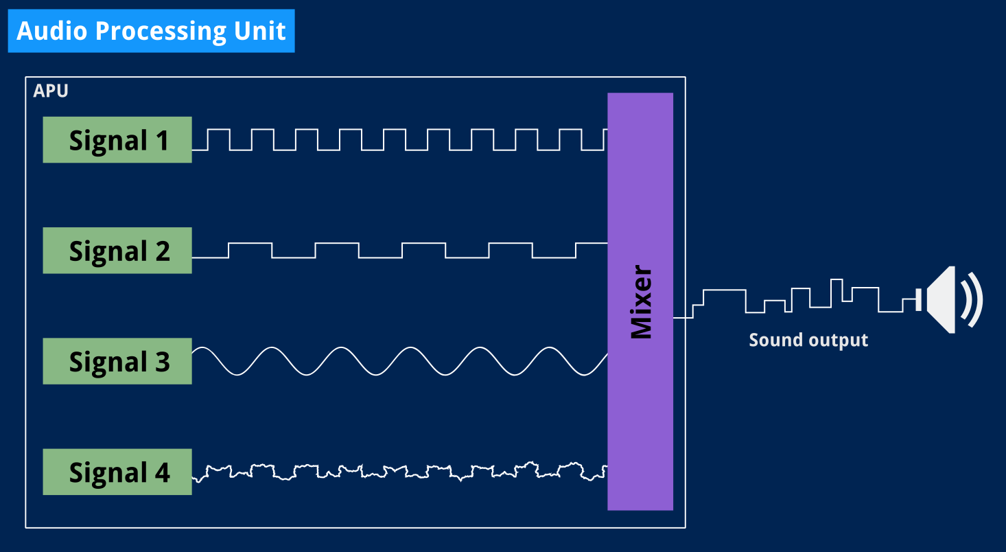
GameBoy circuitry allows producing sound in four different ways:
Quadrangular wave patterns with sweep and envelope functions.

Quadrangular wave patterns with envelope functions.

Voluntary wave patterns from wave RAM.

White noise with an envelope function.
These four sounds can be controlled independently and then mixed separately for each of the output terminals.
Sound registers may be set at all times while producing sound.
…
We are SO not doing all of that today! I still need to explain some of it, though.
In the last article, I focused on square wave signals mostly because I knew we were only going to use the first sound generator in the boot ROM.
It also gets a little confusing because most documents I’ve read refer to those signal generators as “channels” which is a term I already used last time to specifically refer to stereo channels (left and right) so I’ll try and stick to “signal generator” throughout this article, for lack of a better term.
I also might have mentioned it last time but sound, and sound generated by the Game Boy in particular, is complicated. As such, I’ll be glossing over a lot of things in this article. Today’s goal is not even to integrate sound generators in our test emulator yet, but rather to come up with something resembling an emulated sound generator that we’ll first test with last time’s program, which only produced a three-second note.
Okay, where do we even start?
This is a good moment to go back to our original approach and check the boot ROM’s source code to see what is the absolute minimum we need sound-wise.
Here is what the boot ROM does to setup audio:
    LD HL, $ff26     ; $000c  Setup Audio
    LD C, $11        ; $000f
    LD A, $80        ; $0011
    LD (HL-), A      ; $0013  NR52 = $80: All sound on
    LD ($FF00+C), A  ; $0014  NR11 = $80: Wave Duty 50%
    INC C            ; $0015
    LD A, $f3        ; $0016
    LD ($FF00+C), A  ; $0018  NR12 = $f3: Initial volume $0f, Decrease, Sweep 3
    LD (HL-), A      ; $0019  NR51 = $f3: Output sounds 1-4 to S02, 1-2 to S01
    LD A, $77        ; $001a
    LD (HL), A       ; $001c  NR50 = $77: S02-S01 volume 7
And here is where it actually plays sounds:
    LD E, $83        ; $0074
    CP $62           ; $0076  $62 counts in, play sound #1 (E = $83)
    JR Z, Addr_0080  ; $0078
    LD E, $c1        ; $007a
    CP $64           ; $007c
    JR NZ, Addr_0086 ; $007e  $64 counts in, play sound #2 (E = $c1)
Addr_0080:
    LD A, E          ; $0080  Play sound
    LD ($FF00+C), A  ; $0081  NR13 = E: Lower 8 bits of frequency ($83 or $c1)
    INC C            ; $0082
    LD A, $87        ; $0083  NR14 = $87: Higher 3 bits of frequency are 7, and
    LD ($FF00+C), A  ; $0085              the $80 bit starts the sound generator
I added some comments to the code above to better point out which parts of the audio processor we need to implement. It still looks complicated but the actual code does nothing fancy here: it just sets values into registers, and this is something we can already start writing — we’ll deal with the functional bit like starting a sound generator later.
Are you beginning to notice a pattern here?
This will be quick, we have more than enough existing code to deal with even five new registers at once.
I’ve seen it done elsewhere and frankly felt doing the same anyway: we’ll group registers by signal generator and enclose all of that in some APU structure that will hold the control registers.
Like the CPU and PPU, the APU — for Audio Processing Unit — could be considered a state machine with a single state that we’ll tick along with the rest. We’ll just divide stuff, exactly like we did in the previous article, to produce sound samples at the proper speed.
I’ll save us some time and show you the empty Tick() method since that code isn’t particularly different from what we’ve done before.
// SquareWave structure implementing sound sample generation for one of the four
// possible sounds the Game Boy can produce at once. A.k.a Signal 1&2.
type SquareWave struct {
    NR11 uint8 // Pattern duty and sound length
    NR12 uint8 // Volume envelope
    NR13 uint8 // Frequency's lower 8 bits
    NR14 uint8 // Control and frequency' higher 3 bits
}

// Tick produces a sample of the signal to generate based on the current value
// in the signal generator's registers. We use a named return value, which is
// conveniently set to zero (silence) by default.
func (t *SquareWave) Tick() (sample uint8) {

    // TODO: Adjust signal settings depending on register values.
    // TODO: Generate sample here.

    return
}
You can see it’s a not quite a state machine2: the signal generator will always output samples, and we’ll adjust the signal’s parameters on the fly. And we’ve seen last time that generating a square signal doesn’t require all that many parameters.
Ignoring the sampling rate and audio buffer size, which are up to us, we need:
- The signal’s frequency. This is stored in registers NR13 and NR14 as an 11-bit value.
- The volume. This is configured through the NR12 and NR50 registers.
- The signal’s duration. This is normally set in NR11.
The Pan Docs also mention a “duty step” timer, which I assumed would be our running counter for deciding when to switch the signal “on” or “off”. I think this is all we need for now. And all of these things are also more complicated than I anticipated.
Frequency
I mentioned that the tone’s current frequency was stored in registers NR13 and NR14. The Game Boy’s sound generators support 11-bit values for frequencies, which obviously won’t fit in a single 8-bit register, but that’s not the only issue.
You could think that we’re only going to have to do some bitwise operations to fit our frequency in there. For instance, our A from last time is 440 Hz, which clearly doesn’t fit in an 8-bit value that can be at most 255. Using 11 bits, however, the binary value of 440 is 001 10111000. This would mean storing 001 (0x01) in the rightmost three bits of NR14 and 10111000 (0xb8) in NR13.
Let me check the docs real quick…
FF13 – NR13 – Channel 1 Frequency lo (Write Only)
Lower 8 bits of 11 bit frequency (x). Next 3 bit are in NR14 ($FF14).
FF14 – NR14 – Channel 1 Frequency hi (R/W)
Bit 7   - Initial (1=Restart Sound)     (Write Only)
Bit 6   - Counter/consecutive selection (Read/Write)
          (1=Stop output when length in NR11 expires)
Bit 2-0 - Frequency's higher 3 bits (x) (Write Only)
Frequency = 131072/(2048-x) Hz
Wait, what was that thing at the very end?
Oh right! Even with 11 bits, we can only encode values up to 2047, which isn’t very useful if we want to be able to generate frequencies in the whole human hearing range, which is commonly said to go from 20 to 20000 Hz. The given formula, now, produces frequencies between 64 and 131072 Hz3.
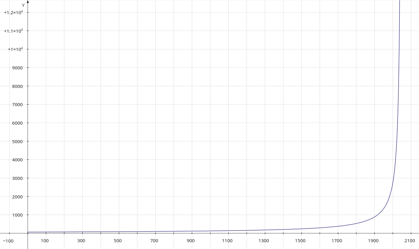
Fair enough! By that formula, then, we need to store 17504 in those registers, that is 11011010110 in binary, so 110 in NR14’s lowest three bits, and 11010110 in NR13.
For reference, the boot ROM code uses the following two values to play the two startup beeps:
- 1923, which translates to 1048.576 Hz
- 1985, which translates to 2080.508 Hz
You can play these tones online or modify the example program from our last article, and they should indeed sound familiar.
Whew. What’s next?
Volume
That part was trivial in the previous article, not so much today. The Game Boy uses registers NR12 and NR50 to control the volume. Let’s see how:
FF12 – NR12 – Channel 1 Volume Envelope (R/W)
Bit 7-4 - Initial Volume of envelope (0-0Fh) (0=No Sound)
Bit 3   - Envelope Direction (0=Decrease, 1=Increase)
Bit 2-0 - Number of envelope sweep (n: 0-7)
          (If zero, stop envelope operation.)
Length of 1 step = n×(1/64) seconds
Oh dear.
This describes a volume envelope which will cause each produced tone to fade out gracefully instead of abruptly cutting off. I’ll leave that aside for the moment. What about NR50?
FF24 – NR50 – Channel control / ON-OFF / Volume (R/W)
The volume bits specify the “Master Volume” for Left/Right sound output. SO2 goes to the left headphone, and SO1 goes to the right.
Bit 7   - Output Vin to SO2 terminal (1=Enable)
Bit 6-4 - SO2 output level (volume)  (0-7)
Bit 3   - Output Vin to SO1 terminal (1=Enable)
Bit 2-0 - SO1 output level (volume)  (0-7)
The Vin signal is an analog signal received from the game cartridge bus, allowing external hardware in the cartridge to supply a fifth sound channel, additionally to the Game Boy’s internal four channels. No licensed games used this feature, and it was omitted from the Game Boy Advance.
You know what? For the time being, I think we’ll save time and stick to our arbitrary volume. I’ll do the volume envelope implementation in the next article.
Whew! Just one left.
Duration
I wrote earlier that sound duration was controlled by NR11, let’s see the specifics:
FF11 – NR11 – Channel 1 Sound length/Wave pattern duty (R/W)
Bit 7-6 - Wave Pattern Duty (Read/Write)
Bit 5-0 - Sound length data (Write Only) (t1: 0-63)

00: 12.5% ( _-------_-------_------- )
01: 25%   ( __------__------__------ )
10: 50%   ( ____----____----____---- ) (normal)
11: 75%   ( ______--______--______-- )
Sound Length = (64-t1)×(1/256) seconds. The Length value is used only if Bit 6 in NR14 is set.
Oh well, it’s actually used for two things: defining the signal’s duty and its length. Moreover, there’s another hint at the end telling us the length value might not even be used, and if you check what’s written to NR14 in the Game Boy boot ROM, you’ll notice that bit 6 is actually not set.
Looks like we’ll need to use the volume envelope to control duration after all. Bummer. The good news is that implementing duty patterns isn’t too complicated so we’ll do that today instead of volume envelopes. Deal?
We still have a lot of work to do.
No, seriously, where do we start?
We’re clearly not going to be able to do all of that in this one article. Let’s stick to using arbitrary frequency values and somehow turn them into sound. I’ll hardcode the volume and duration like we did last time, and I’ll be looking at the volume envelope later.
In fact, I first thought I’d do without the whole duty cycle thing altogether, but I’ve stumbled upon documentation that describes it in a way I found easy to implement, so we’ll actually start with that.
Duty
So!
A sound signal generator should generate a signal, right? Keeping with our example from last time, that generator will produce the on/off value that we want dynamically, depending on the frequency it’s programmed to generate. But instead of our manual sample count from last time, the generator will have to compute how many samples it should output before it switches the signal between on and off.
Now, rather than reusing our simple formula5, we’re going to follow another bit of documentation from the GB Dev wiki:
Square Wave
A square channel’s frequency timer period is set to (2048-frequency)×4. Four duty cycles are available, each waveform taking 8 frequency timer clocks to cycle through:
Duty   Waveform    Ratio
-------------------------
0      00000001    12.5%
1      10000001    25%
2      10000111    50%
3      01111110    75%
I’ll admit it, that formula they gave for the frequency timer didn’t make sense to me at first. So, like last time, I tried figuring it out again from scratch.
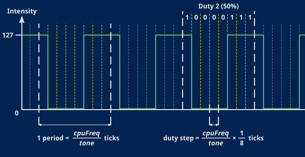
What we want to achieve is slicing one period of our signal in 8. Then, for each 8th of a period, blindly use the corresponding duty bit to decide whether the signal should be on or off.
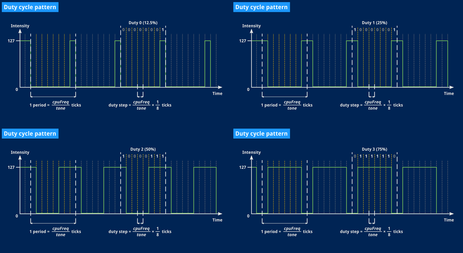
Now that seems easy, I like it, no need to compute anything but that 8th of a period, and then just advance through the waveform bits6.
And that formula? Well, assuming tone is our signal’s actual frequency, and keeping in mind that the only clock we use is our CPU, that 8th of a period will occur every CPUfreq / tone / 8.
If you replace the proper terms in that equation (and believe me, at this point I didn’t even bother and let The Internet do the whole thing for me) you end up with… (2048 – tone) × 4, woo!
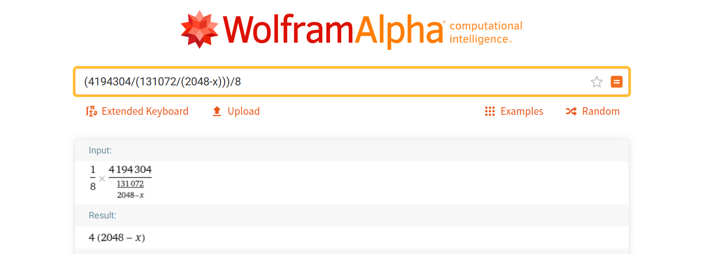
Note that we no longer use the sampling rate, here. It will come up later, when we decide whether the latest sample frame computed by the APU should be sent to the sound device.
What I’m really trying to express is that things will tick at various rates and we’ll use the fastest of these things, in our case the CPU at 4 MHz, as a base to time all the other ticks.
For instance, outputting sound samples should happen 22100 times a second, which is every 4194304/22100 CPU ticks. By keeping all these tick timings relative to one another, we can hopefully achieve some accuracy for the whole emulator by managing to run our 4 MHz clock at, well, as close to 4 MHz as we can manage.
Let’s revisit our generator’s empty Tick() method from earlier and add a few constants:
// GameBoyRate is the main CPU frequence to be used in divisions.
const GameBoyRate = 4 * 1024 * 1024 // 4194304Hz or 4MiHz

// DutyCycles represents available duty patterns. For any given frequency,
// we'll internally split one period of that frequency in 8, and for each
// of those slices, this will specify whether the signal should be on or off.
var DutyCycles = [4][8]bool{
	{false, false, false, false, false, false, false, true}, // 00000001, 12.5%
	{true, false, false, false, false, false, false, true},  // 10000001, 25%
	{true, false, false, false, false, true, true, true},    // 10000111, 50%
	{false, true, true, true, true, true, true, false},      // 01111110, 75%
}

func (s *SquareWave) Tick() (sample uint8) {
	// With `x` the 11-bit value in NR13/NR14, frequency is 131072/(2048-x) Hz.
	rawFreq := ((uint(s.NR14) & 7) << 8) | uint(s.NR13)
	freq := 131072 / (2048 - rawFreq)

	// Advance duty step every f/8 where f is the sound's real frequency.
	if s.ticks++; s.ticks >= GameBoyRate/(freq*8) {
		s.dutyStep = (s.dutyStep + 1) % 8
		s.ticks = 0
	}

	// TODO: Compute volume for real. Cheat for now.
	if DutyCycles[s.dutyType][s.dutyStep] {
		sample = Volume // Arbitrary volume for testing
	}

	return
}
The astute reader will notice that we also added the dutyType and dutyStep properties to our signal generator. The former should be defined by NR11’s bits 6 and 7 (“Wave Duty”) but we’ll set it manually for now, and the latter is just an internal counter that will continuously loop from 0 to 7.
Right now, this is actually all we need to generate a single audio signal!
Stereo
Since we’re postponing volume and duration implementation, let’s at least try and output sound on our two stereo channels. It turns out to be quite straightforward now that we have a dedicated state machine to generate samples!
In fact, I’ll show the code for our current APU structure below. It’s deceptively simple:
// SoundOutRate represents CPU cycles to wait before producing one sample frame.
const SoundOutRate = GameBoyRate / SamplingRate

// APU structure grouping all sound signal generators and keeping track of when
// to actually output a sample for the sound card to play. For now we only use
// two generators for stereo sound, but in time, we'll mix the output of four of
// those and the stereo channel they'll go to will be configurable as well.
type APU struct {
	ToneSweep1 SquareWave
	ToneSweep2 SquareWave

	ticks uint // Clock ticks counter for playing samples
}

// Tick advances the state machine of all signal generators to produce a single
// stereo sample for the sound card. This sample is only actually sent to the
// sound card at the chosen sampling rate.
func (a *APU) Tick() (left, right uint8, play bool) {
	// Advance all signal generators a step. Right now we only have two but
	// if we were to implement all four, we'd actually mix all their outputs
	// together here (with various per-generator parameters to account for).

    // Here we also cheat a bit and force the first generator's output to the
    // left channel, and the second generator's output to the right.
	left = a.ToneSweep1.Tick()
	right = a.ToneSweep2.Tick()

	// We're ticking as fast as the Game Boy CPU goes, but our sound sample rate
    // is much lower than that so we only need to yield an actual sample frame
    // every so often.
	if a.ticks++; a.ticks >= SoundOutRate {
		a.ticks = 0
		play = true
	}

	return
}
Yep. That’s it! If we make that APU tick at the same frequency as our emulator’s CPU, it will compute samples at every tick but will only request samples to be actually played when needed, that is, whenever enough CPU ticks have elapsed to cover 1/22100 seconds7.
Callback in time
And now the only thing missing is to actually send those samples to the sound device. Fortunately that part of the code is pretty much copy-pasted from our last article. I only trimmed comments down a bit for brevity, but I still kept all the code we used to display timings.
// Audio callback function that SDL will call at a regular interval that
// should be roughly <sampling rate> / (<audio buffer size> / <channels>).
//
//export squareWaveCallback
func squareWaveCallback(data unsafe.Pointer, buf *C.Uint8, len C.int) {
	// SDL bindings shenanigans.
	n := int(len)
	hdr := reflect.SliceHeader{Data: uintptr(unsafe.Pointer(buf)), Len: n, Cap: n}
	buffer := *(*[]C.Uint8)(unsafe.Pointer(&hdr))

	// Tick the APU as many times as needed to fill the audio buffer. In the
	// end we'll actually tick the whole emulator here (CPU, PPU and APU) but
	// not every tick will produce a sample.
	for i := 0; i < n; {
		left, right, play := apu.Tick()
		if play {
			buffer[i] = C.Uint8(left)
			buffer[i+1] = C.Uint8(right)
			i += 2
		}
	}

	// Count sample frames to know when the desired number of seconds has
	// elapsed, then tell the main function we want to quit.
	sampleFrames += uint(n / 2)
	if sampleFrames >= SamplingRate*Duration {
		quit = true
	}

	// Store current ticks count for later computations.
	ticksInCallback = append(ticksInCallback, int(sdl.GetTicks()))
}
The only bit that’s changed from last time is the contents of that for loop. Now, instead of manually computing whether our signal should be on or off, we trust the signal generator and let it do its thing.
This is the last stretch! All that’s needed now is to update our main() function with a little setup to put the proper values in our new registers.
Let there be sound (again)!
In the previous article, we did all the work from within the callback and our main values were global constants. This time we need to add the following initialization code to our main function, pretty much anywhere before we enable sound playback. We’ll do this by hand today but next time, the emulator itself will put the needed values in those APU registers!
	// ... rest of main() function above ...

	// Use global variable for the callback for now. What I want to do may not
	// be possible here. I have a plan B. It's fine.
	apu = &APU{}

	// Simulate sound being enabled. Again, I only want to see if sound comes
	// out for now. We need to store our tone's frequency as 131072/(2048-f) in
	// 11-bits. Frequency obviously cannot be zero. We can also pick a duty type
	// (default is 0, i.e. 12.5%).

	// Output the tone defined in our constants to the left channel.
	toneLeft := Tone
	rawFreq := (2048 * (toneLeft - 64)) / toneLeft

	// Lowest 8 bits of calculated frequency in NR13.
	apu.ToneSweep1.NR13 = uint8(rawFreq & 0x00ff)

	// Highest 3 bits of calculated frequency. Note that bit 6 is still zero,
	// so we're not using NR11 to control the length of that note. This won't
	// really matter until next article.
	apu.ToneSweep1.NR14 = uint8(rawFreq & 0x0700 >> 8)
	apu.ToneSweep1.dutyType = 2 // 50% duty

	// Output tone/3 to the right channel. This should sound okay. You can set
	// the new tone to the original toner ×2 or divide it by 2, or play around
	// with other values, change the duty type, etc.
	// I have to admit that when I finally got to this point I gleefully tried
	// many truly horrific combinations.
	toneRight := toneLeft / 3
	rawFreq = (2048 * (toneRight - 64)) / toneRight
	apu.ToneSweep2.NR13 = uint8(rawFreq & 0x00ff)
	apu.ToneSweep2.NR14 = uint8(rawFreq & 0x0700 >> 8)
	apu.ToneSweep2.dutyType = 2

	// Start playing sound.
	sdl.PauseAudio(false)

	// ... rest of main() function below ...
I’m still using a global pointer for our APU instance because I haven’t figured out a satisfactory way to pass it to the callback as a data pointer8.
Other than that, I’m merely setting register values. Oh, and in case you’re wondering where that formula to convert the frequency into our 11-bit value comes from:
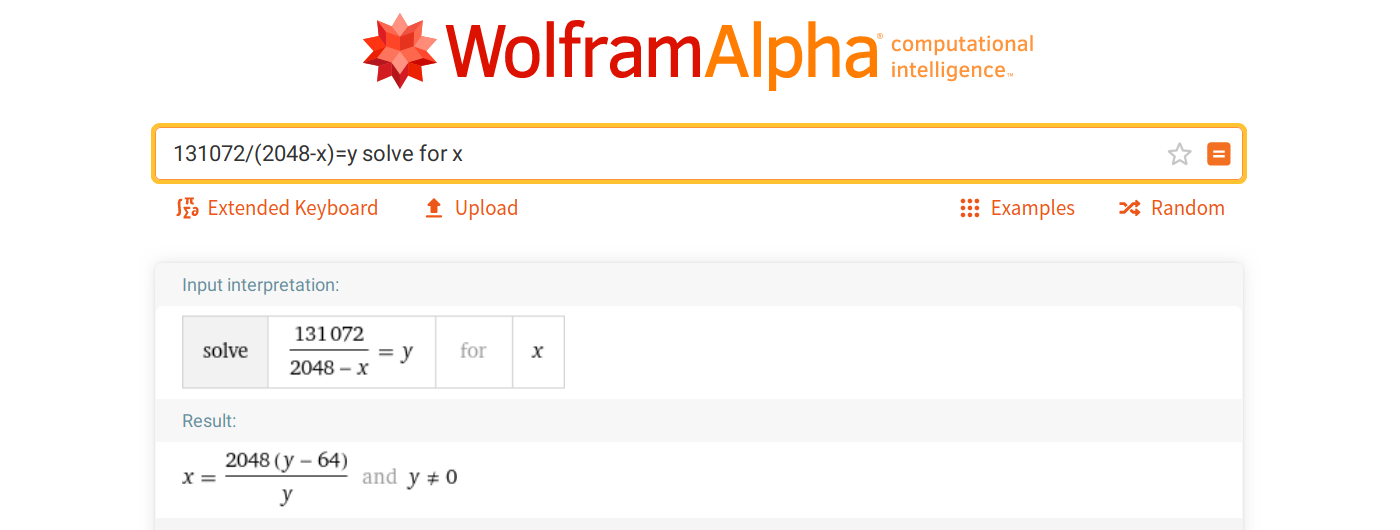
Erm.
I think that’s all of it. Let us give it a try, shall we?
This sounds very similar to last time, but about twice as interesting! Granted, we’re cheating here, this isn’t true polyphony, we’re just playing a single sound on different channels.
What would happen if we wanted to play a third note? A fourth?
Will it blend?
I mean, we have the whole machinery ready, I could easily add as many SquareWave objects as I’d like to our APU, but we’ve already run out of stereo channels to play sounds.
We need to mix these together. And I initially thought it would deserve its whole article because, surely, mixing sound signals has got to be complicated, right?
A quick search later, it quickly became apparent that I was wrong. There are subtleties to it of course, but in a pinch, I could just add another generator to the APU:
type APU struct {
	ToneSweep1 SquareWave
	ToneSweep2 SquareWave

	// We could add even more generators for the fun of it!
	ToneSweep3 SquareWave

	ticks uint // Clock ticks counter for mixing samples
}
… then initialize it just like the others:
	// ...

	// Why stop here? We can add yet another harmonic if we feel like it! Even
	// use a different duty pattern.
	toneExtra := toneLeft / 4
	rawFreq = (2048 * (toneExtra - 64)) / toneExtra
	apu.ToneSweep3.NR13 = uint8(rawFreq & 0x00ff)
	apu.ToneSweep3.NR14 = uint8(rawFreq&0x0700>>8)
	apu.ToneSweep3.dutyType = 3

	// Start playing sound. Not sure why we un-pause it instead of starting it.
	sdl.PauseAudio(false)

	// ...
… and in the end, do just this in the APU’s Tick() method:
	// ...

	// Another way to use the generated sound is to mix it and send the result
	// to both stereo channels. I'm pretty sure there are limitations to this
	// but in the mean time, we can still do this:
	left = a.ToneSweep1.Tick() + a.ToneSweep2.Tick() + a.ToneSweep3.Tick()
	right = left

	// ...
I wasn’t all that convinced, but then I tried it out, and…
… okay, this is one less thing to worry about for now!
I’ll admit I spent a whole evening trying out different combinations — with mitigated results, sure, but that was really fun!
I’ll be honest, too: that you can so simply9 add samples together still feels like magic to me.
But hey, it works, and though I won’t cover that specific topic, I still found a good resource explaining why and how it works!
“Are we there yet?”
We’re close!
I expect we’ll cover the volume envelope in the next article, and that should hopefully be enough for us to integrate all that sound machinery in our example emulator.
Also, I know that all audio examples shown here don’t sound too great, but there is some potential room for improvement. I already got slightly better results with higher sampling rates. However, for the time being, I can live with those 22050 herz.
(Spoiler alert: as I was procrastinating instead of finishing this article, I actually ported the present sound code to Goholint. Threading issues and volume envelope aside, it worked really well, and I hope it will work as well with our example code.)
As always, thank you for reading!
References
- Ultimate Game Boy Talk (sound processor)
- Pan Docs (sound overview)
- Envelope (Music)
- GB Dev Wiki (square wave duty)
- WolframAlpha (I really suck at math)
- Online Tone Generator
- Adding Signals
- Example program: sound is still complicated
You can download the example program above and run it anywhere from the command line:
$ go run sound-is-still-complicated.go
-
Also 2020 has not been kind so it’s been a long while since I worked on the emulator or these articles and I need to get back into it. ↩︎
-
The Pan Docs have a great tl;dr in the Audio Details section: “The PPU is a bunch of state machines, and the APU is a bunch of counters.” ↩︎
-
With some caveats due to rounding that I, as announced earlier, will not go into. The updated Pan Docs contain some more details. Spoiler alert: they are complicated. ↩︎
-
Technically 96256/55 but this is going to be close enough. ↩︎
-
Sampling Rate / Note Frequency, which, for our pure note was 22050 / 440 ≈ 50 ↩︎
-
You might have noticed that the duty cycle doesn’t exactly start on a rising or falling edge but is slightly offset. I’m not entirely sure why, but my best guess is that it sounds better when you start mixing several signals with similar frequencies but different duties. If you know more, I’d be delighted to hear further details! ↩︎
-
This method is very suboptimal, but it was conceptually simple enough to help me make sound work at all. Optimizing it is left as an exercise for the reader. (2024 edit: the reader did do the exercise and actually fixed a lot of sound issues in Goholint. Thank you, reader. ♥) ↩︎
-
Some obscure internal restrictions involving C-pointers and Go-pointers. There are golang libraries to fix that, I’ll look into them at some point. This is, as usual, totally irrelevant to the rest of this article anyway. ↩︎
-
I realize it took a shitload of work to get to this specific point, but then that last little bit felt simple! ↩︎
