Writing an emulator: the first (real) pixel
All right, I promised you pixels in the last article, and while we did end up displaying a full frame, those pixels were a little underwhelming and blocky1.
Fortunately, the whole PPU we wrote last time needs very little extra code to move from the command-line realm into actual windows and more regular pixels (even though we’ll still probably want to stretch them a bit for visual comfort).
The real obstacle here isn’t quite writing code yet — although, as promised last time, I did implement the remaining CPU instructions that were missing in our example program so you don’t have to — but deciding which tools we’re going to use.
How do you even pronounce “GUI”?2
GUI stands for Graphical User Interface, and I’ll use the term as opposed to CLI (Command Line Interface) which is what we’ve been doing all along so far. Now, when reading about GUIs, depending on your age, you might think about windows with menus and keyboard shortcuts, or apps with buttons or even console-based interfaces with the same block characters we used in our very code!
The one thing all those GUIs have in common is that they allow some measure of interaction with the end user, through peripherals like a keyboard, a mouse or a touchscreen, while displaying everything within a dedicated window. And this is pretty much what we want: some tool that will let us work with an arbitrary rectangular area on screen and draw individual dots on it, in the color we desire, while accepting inputs from the user.
Now, I’m no game developer, but I’ve run enough games to be aware of a few of those tools, even just by name. You know, stuff like OpenGL, Direct3D… the kind of engines you’d see used by real-world games. Since my primary target is Linux, I initially had a look at OpenGL, but it was way too complicated for me3.
That being said, a college friend and I did write a game years ago4, which used the Qt framework and most notably QGraphicsScene. It worked okay but could run pretty slow on lower-end systems. This is one reason why I haven’t really looked into Qt either this time around. I feared this might be too high-level for my purpose5.
What I did remember was how many of the Linux games I played back in the day ran using SDL, and they ran pretty well on the unimpressive laptop I had back then. With that bias in mind, I started looking into SDL, found out there were bindings for Go and that they were a lot more user-friendly than the raw OpenGL API. Moreover, the documentation seemed to hint that SDL would allow me to do exactly what the PPU needed.
If your game just wants to get fully-rendered frames to the screen
A special case for old school software rendered games: the application wants to draw every pixel itself and get that final set of pixels to the screen efficiently in one big blit. An example of a game like this is Doom, or Duke Nukem 3D, or many others.
(This was pretty much what I wanted already, but I have to confess that they really had me a bit further down, at “…or just malloc() a block of pixels to write into.”)
The only issue is that SDL isn’t really made for building high-level GUIs, there’s no easy way to add menus, buttons and other widgets to a window… However, it’s more than enough to output pixels and sound while accepting keyboard inputs, none of which is covered by our example program so far.
Working with textures
Now, my knowledge of 3D-related stuff is pretty limited, so I’ll use the word “texture” rather liberally in this article. I’ll consider it as a memory zone containing raw pixel data for an arbitrary rectangular area. This is what SDL is letting us work with anyway. As for pixel data, I’ll assume that each pixel can be represented as four bytes: one for the red value, one for the green value, one for the blue value and the last one for transparency (a.k.a. alpha channel). This is called RGBA and it’s a pretty common way to represent colors6.
For our 160×144 Game Boy screen, that amounts to a single 92160-byte texture buffer. The nice thing is that, as far as SDL is concerned, our pixels are stored sequentially in that buffer from top-left to bottom right.
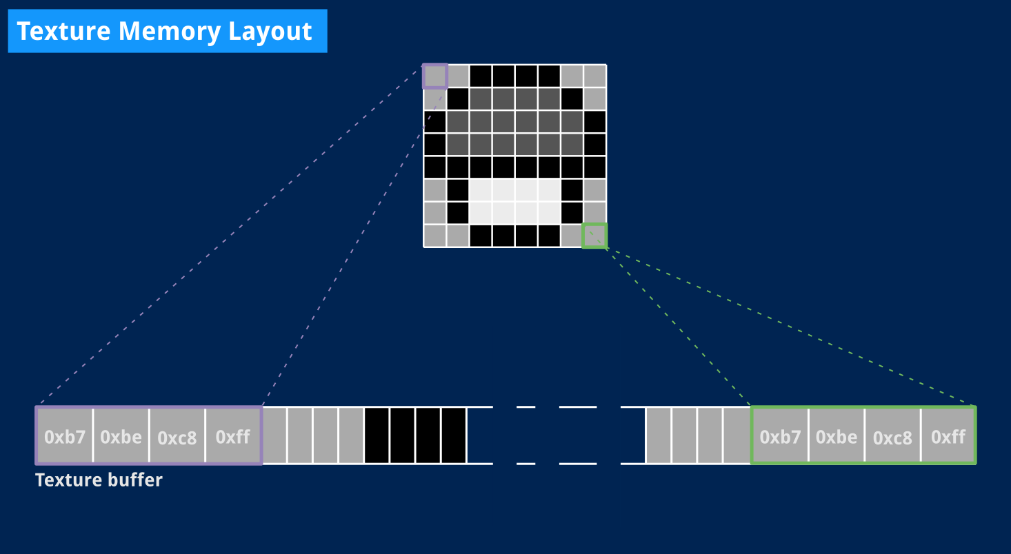
This is actually quite similar to our Console screen, and you should already see how we’ll simply change the way Write() and VBlank() work: instead of printing out a character, we can add pixel data to our buffer. The main difference is that we’ll actually display the whole picture on screen at V-Blank time. And the best thing about it is that the whole code we need is already available on the SDL wiki.
In fact, I pretty much got started by adapting the example code from the SDL_CreateTexture documentation. That code snippet shows what’s needed to work with an SDL texture:
- A window to display our pixels.
- A renderer that will roughly act as some black box abstracting your computer’s GPU.
- A texture that will contain pixel data for a single frame.
A slightly more complex screen
The original code is C, but is easily translated to Go. And like last time, we’ll put all of that in a dedicated structured type that satisfies the Display interface we already defined.
// SDL display shifting pixels out to a single texture.
type SDL struct {
    // Palette will contain our R, G, B and A components for each of the four
    // potential colors the Game Boy can display.
    Palette  [4]color.RGBA

    // The following fields store pointers to the Window, Renderer and Texture
    // objects used by the SDL display.
    window   *sdl.Window
    renderer *sdl.Renderer
    texture  *sdl.Texture

    // The texture buffer for the current frame, and the current offset where
    // new pixel data should be written into that buffer.
    buffer   []byte
    offset   int
}
The structure itself isn’t so different than our console display from last time. We’ll just write to a byte array rather than standard output and there is a little extra bookkeeping purely related to SDL itself. We’re also using Go’s native RGBA type to represent pixel shades7.
Initialization, now, requires a little more code, but the implementation below was mostly copied over from the SDL documentation (with, once again, error handling omitted for clarity). We also define a few constants for readability and convenience: a palette of four greenish colors and the screen’s dimensions.
// DefaultPalette represents the selectable colors in the DMG. We use a greenish
// set of colors and Alpha is always 0xff since we won't use transparency.
var DefaultPalette = [4]color.RGBA{
    color.RGBA{0xe0, 0xf0, 0xe7, 0xff}, // White
    color.RGBA{0x8b, 0xa3, 0x94, 0xff}, // Light gray
    color.RGBA{0x55, 0x64, 0x5a, 0xff}, // Dark gray
    color.RGBA{0x34, 0x3d, 0x37, 0xff}, // Black
}

// Screen dimensions that will be used in several different places.
const (
    ScreenWidth  = 160
    ScreenHeight = 144
)

// NewSDL returns an SDL display with a greenish palette.
func NewSDL() *SDL {
    // Create the window where the Game Boy pixels will be drawn.
    window, _ := sdl.CreateWindow("The first (real) pixel",
        sdl.WINDOWPOS_UNDEFINED, // Don't specify any X or Y position
        sdl.WINDOWPOS_UNDEFINED,
        ScreenWidth*2, ScreenHeight*2, // ×2 zoom
        sdl.WINDOW_SHOWN) // Make sure window is visible at creation time

    // Create the renderer that will serve as an abstraction for the GPU and
    // output to the window we just created.
    renderer, _ := sdl.CreateRenderer(window,
        -1,                       // Auto-select what rendering driver to use
        sdl.RENDERER_ACCELERATED) // Use hardware acceleration if possible

    // Create the texture that will be used to draw the Game Boy's screen.
    texture, _ := renderer.CreateTexture(
        // We want to store RGBA color values in our texture buffer.
        uint32(sdl.PIXELFORMAT_RGBA32),

        // Tell the GPU this texture will change frequently, since we'll update
        // it once every frame.
        sdl.TEXTUREACCESS_STREAMING,

        // The texture itself is exactly the size of the Game Boy screen,
        // 160×144 pixels. The renderer will stretch it as needed to fit our
        // window's actual size.
        ScreenWidth, ScreenHeight)

    // 160×144 pixels stored using 4 bytes each (as per RGBA32) give us the
    // exact size we need for the texture buffer.
    bufLen := ScreenWidth * ScreenHeight * 4
    buffer := make([]byte, bufLen)

    sdl := SDL{Palette: DefaultPalette, renderer: renderer, texture: texture,
        buffer: buffer}

    return &sdl
}
Not much going on there: we create a window, attach a renderer to it and then create a single texture for that renderer which we’ll update every frame. There is some underlying magic I’m not going to go into, like texture access type and some other flags, because I’m honestly not entirely sure I understand the specifics at this time. I’m trusting SDL’s example code on this.
There are, however, still a couple subtleties:
- We applied a ×2 factor to the window’s size. SDL itself will take care of resizing the texture, so our code can safely assume it’s working with a 160×144 rectangle, no matter what the actual window size is.
- We’re using the RGBA32 texture format. I have to admit it took me a little trial-and-error to come up with the proper setting because endianness is a bitch, but Wikipedia actually has a helpful section on that topic that I only discovered recently.
- We instantiate a texture buffer that takes four bytes per pixel, to conform to the RGBA32 format.
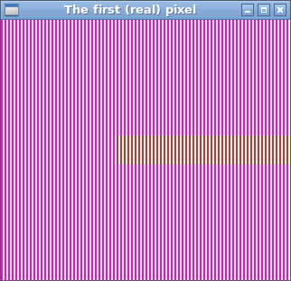
Next, we have to implement Write(), HBlank() and VBlank() to satisfy the Display interface.
Updating the texture
We’ll start with Write(), which conceptually works as for our Console version: we’ll look up a pixel color in our RGBA palette and append the corresponding four bytes to the texture buffer.
// Write adds a new pixel to the texture buffer.
func (s *SDL) Write(colorIndex uint8) {
    color := s.Palette[colorIndex]

    s.buffer[s.offset+0] = color.R
    s.buffer[s.offset+1] = color.G
    s.buffer[s.offset+2] = color.B
    s.buffer[s.offset+3] = color.A

    s.offset += 4
}
The real difference with our Console display is that nothing is sent to the screen yet. If you were to introduce some large delay in the Console implementation of Write(), you could see each “pixel” being output to screen individually. Not here. We need the whole frame to be complete before we can display it. We’ll do that in the VBlank() method. This also means that our SDL display will have an empty HBlank() method.
Putting real pixels on screen at last
Now that our buffer contains fresh pixels for the latest frame, we need to ask SDL to display them.
// VBlank is called when the PPU reaches VBlank state. At this point, our SDL
// buffer should be ready to display.
func (s *SDL) VBlank() {
    s.offset = 0    // Reset offset for next frame

    // Update the texture buffer with our data.
    s.texture.Update(
        nil,           // Rectangle to update (here, the whole texture)
        s.buffer,      // Our up-to-date texture buffer
        ScreenWidth*4, // The texture buffer's "pitch" in bytes
    )

    // Display the complete updated texture on screen.
    s.renderer.Copy(s.texture, nil, nil)
    s.renderer.Present()
}
The way SDL works, you call Update() on the texture object with your new texture buffer. It’s possible to only update parts of a texture, so you could conceivably define a smaller rectangular area to update, but we’ll always want to update the whole texture at once, here.
The Update() method also needs to know the buffer’s “pitch”, that’s the width of the texture area, expressed in bytes. See, our texture buffer is only a long list of contiguous bytes. We know the texture itself is 160×144, which you can describe as 144 lines, each made up of 160 pixels, each pixel represented with 4 bytes.
But as far as SDL is concerned, this could just as well be 160 lines containing 144 pixels. Or 80 lines each made up of 288 pixels, and so on. So we tell SDL that this 92160-byte texture buffer should be sliced into lines 144 pixels wide, that is 144×4 bytes.
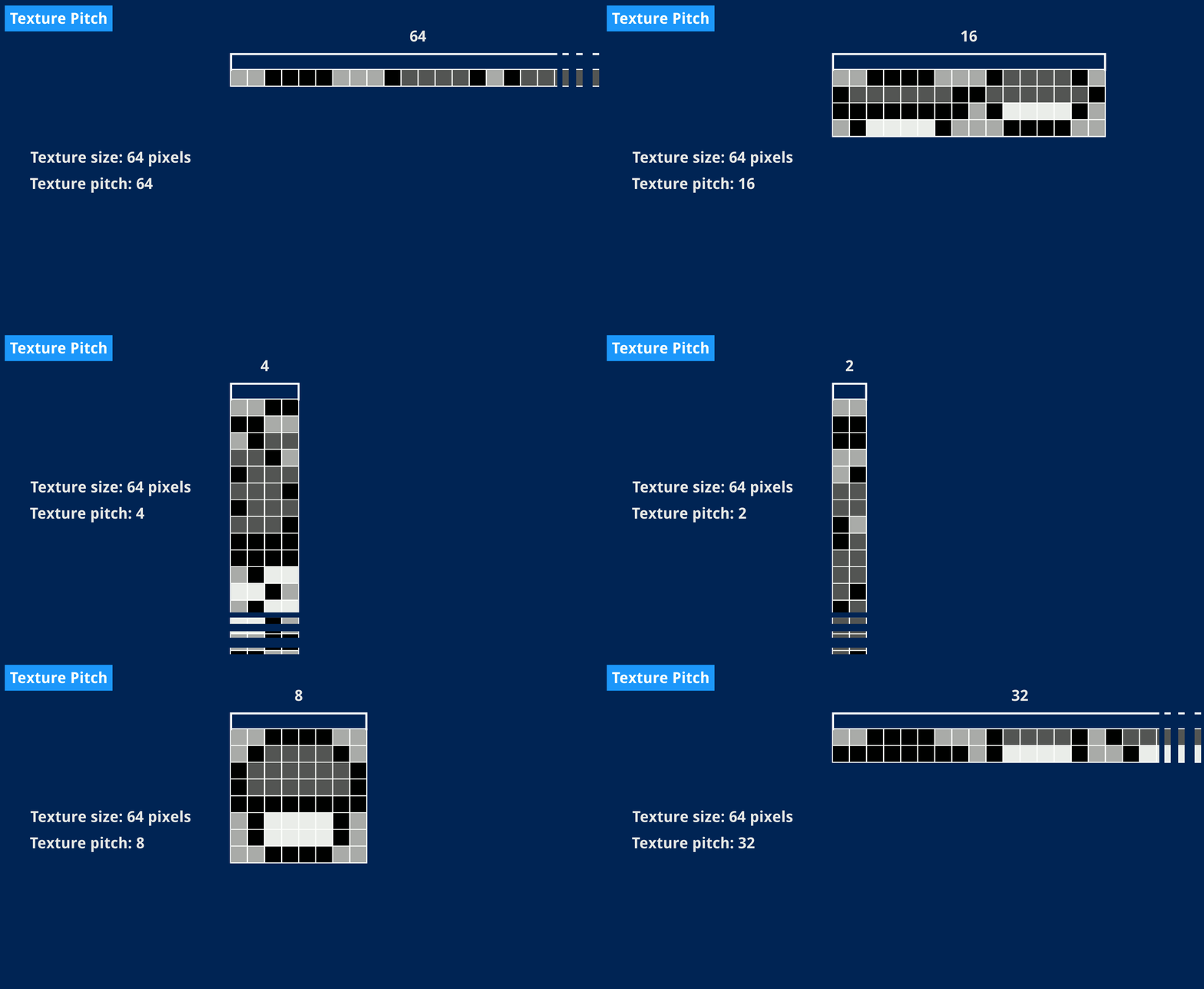
Once the texture is ready, we send it to the renderer using Copy(). Again, we’re not doing anything interesting or fancy here because we only care about our whole texture and the rendering target isn’t used for anything else. But we could also update smaller areas of the rendering target if we wanted to.
And then we can tell SDL to put those pixels on screen. This is done by calling Present() on the renderer, which will repaint the content of our SDL window with the current texture.
Trying it out
Just call NewSDL() instead of NewConsole() in our main function, then we’re ready to see if it works.
    // Create window and set is as the PPU's display.
    screen := NewSDL()
    ppu := NewPPU(screen) // Covers 0xff40, 0xff44 and 0xff47
And behold!
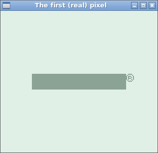
That’s more like it. An actual window. Proper pixels! And the program no longer exits on its own — you actually need to stop it with CTRL+C from the terminal, now.
There are still a couple issues that we haven’t fixed from last time:
- We’re still seeing the logo right away instead of seeing it scroll down.
- That bar is definitely not the right color. It’s supposed to be the darkest shade the Game Boy can display, and it clearly isn’t.
I’ll start with the latter, which is going to be rather quick to fix.
What’s in a tile?
If we directly translated tile data from video RAM to the screen, why is the color off?
That’s because I blindly and directly used the value I read from video RAM (really just a number between 0 and 3) as a color — 0 for white, 1 for light gray, 2 for dark gray and 3 for black8. Except I should have used that value as an index into a palette.
What’s a palette, in the Game Boy memory? It’s only a byte, which contains four 2-bit color values (really just numbers between 0 and 3) which you can access as if they were stored in an array by using an index between 0 and 3.
That’s a lot of numbers between zero and three, hence my initial confusion. The point here is that pixel values stored in video RAM, no matter if they’re part of a sprite or a background tile, don’t represent actual colors but only a color number into a user-defined palette. This is useful in several ways.
For instance, the boot ROM only needs two colors: the lightest for the background, and the darkest for the scrolling logo.
Going with my initial assumption, you’d expect white pixels to be stored in memory as the value 0, and black pixels as the value 3. It’s a little more complicated than that since, as we saw last article, the Game Boy doesn’t deal with single pixels but rows of eight, each needing two bytes since two bits are needed for each of the 8 pixels in that row.
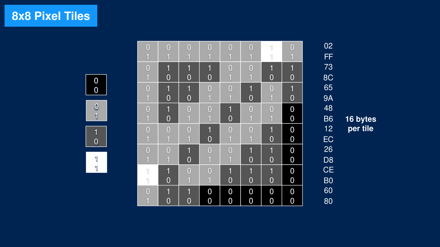
In our context, a white pixel’s binary value would be 00 (color number 0), and a black pixel’s 11 (color number 3). A full row of white pixels would be stored as 0x00 0x00, a full row of black pixels as 0xff 0xff. A completely white tile would be sixteen consecutive 0x00 bytes, and a fully black tile would be sixteen consecutive 0xff bytes.
But if that was the case, then we’d read those values from video RAM and the black bar we displayed should be the darkest color. So what is actually stored in video RAM?
Dumping RAM values is slightly out of the scope of this article, so I’ll skip to the result. Here is what tile data looks like in memory9. Keep in mind that those tiles are normally read from the cartridge itself. Since we don’t have one yet, our MMU always returns 0xff when attempting to read from that memory location, and I would expect to see only 0xff bytes in there.
00008000  00 00 00 00 00 00 00 00  00 00 00 00 00 00 00 00
00008010  ff 00 ff 00 ff 00 ff 00  ff 00 ff 00 ff 00 ff 00
*
Wait, what?
The first sixteen bytes starting from 0x8000 are at least consistent with our initial intuition: they’re all zero, and they’re actually used to define the white background tiles.
However, the next tiles are all the same: 0xff 0x00, which amounts to eight pixels whose color value, on two bits, is 01 — first byte contains the least-significant, a.k.a rightmost bit, I keep telling you endianness is a pain.
This explains why the color is off: we’re outputting pixels with color value 1, the lightest shade of gray, instead of 3, the darkest.
This article is already too long for me to explain why those tiles are stored in memory this way, but I’d love to, and I’ll definitely cover it at some point. In short, the Nintendo logo is stored in a compact format inside the cartridge, and the boot ROM code applies some treatment to it before storing the final tiles in video RAM. When it does, since the final logo only uses a single color anyway, only one byte of tile data is written (the 0xff one).
Why not write two 0xff bytes while the boot ROM code is at it? Well, doing so would require writing to memory twice as many times, which would use an extra instruction in a boot ROM that’s a tight fit already, just to make the whole logo appear in another color. It turns out the Game Boy can do much better.
The background palette (BGP)
Be it light, darker or darkest, that logo — or lack thereof, I guess — we just displayed is still one single, uniform color: all of its non-white pixels have the same color number. And as it happens, the Game Boy treats that value as an index instead of a fixed color. This means that we decide what color is 01. And we do that by changing the background palette register (a.k.a BGP).
This register is part of the PPU, and as usual, I’ll let the Pan Docs do the talking.
FF47 — BGP (Non-CGB Mode only): BG palette data
This register assigns gray shades to the color IDs of the BG and Window tiles.
7-6 5-4 3-2 1-0 Color for… ID 3 ID 2 ID 1 ID 0 Each of the two-bit values map to a color thusly:
Value Color 0 White 1 Light gray 2 Dark gray 3 Black
So, that color number between 0 and 3 simply maps to another number between 0 and 3, but the latter is entirely up to us. And sure enough, look at the beginning of the boot ROM assembly code:
    LD A, $fc           ; $001d  Setup BG palette
    LD ($FF00+$47), A   ; $001f
Ah, ha! It’s storing the value 0xfc in that 0xff47 register.
In binary, 0xfc is 11 11 11 00, defining shades for color numbers 3, 2, 1 and 0 respectively. It means that color number 0 is white, and all other color numbers map to 3, black. And now it all makes sense: color number 1, in that palette, maps to bits 3-2 which are 11, the black shade we actually expected.
(Among other things, this mechanism also allows nice color effects by only changing the palette entries themselves without ever needing to modify tile data in memory.)
A quick fix
Okay, I might have written “rather quick to fix” a little hastily earlier, but now we know what the problem is, I promise it won’t require much code at all. It’s just a new register to add to the PPU. We’ve done that before with LY. Just add an 8-bit register to the PPU struct.
type PPU struct {
    LCDC uint8 // LCD Control register.
    LY   uint8 // Number of the scanline currently being displayed.
    BGP  uint8 // Background map tiles palette.

    // ... other fields omitted ...
}
Then adjust the Contains(), Read() and Write() methods to add BGP to the PPU’s exposed address space. Adding support for the 0xff47 address requires only four extra lines of code.
// Contains return true if the requested address is LCDC, LY or BGP.
// We'll soon come up with a way to automatically map an address to a register.
func (p *PPU) Contains(addr uint16) bool {
    return addr == 0xff40 || addr == 0xff44 || addr == 0xff47
}

// Read returns the current value in LCDC, LY or BGP register.
func (p *PPU) Read(addr uint16) uint8 {
    switch addr {
    case 0xff40:
        return p.LCDC
    case 0xff44:
        return p.LY
    case 0xff47:
        return p.BGP
    }
    panic("invalid PPU read address")
}

// Write updates the value in LCDC or BGP and ignore writes to LY.
func (p *PPU) Write(addr uint16, value uint8) {
    switch addr {
    case 0xff40:
        p.LCDC = value
    case 0xff44:
        // LY is read-only.
    case 0xff47:
        p.BGP = value
    default:
        panic("invalid PPU write address")
    }
}
Now all that’s left to do is translating our pixel color number to an actual shade from the background palette before writing it to the screen, as part of the PPU’s PixelTransfer state. This is summed up with some bit shift arithmetic.
    // Put a pixel from the FIFO on screen. We take a value between 0 and 3
    // and use it to look up an actual color (yet another value between 0
    // and 3 where 0 is the lightest color and 3 the darkest) in the BGP
    // register.
    pixelColor, _ := p.Fetcher.FIFO.Pop()

    // BGP contains four consecutive 2-bit values. We take the one whose
    // index is given by pixelColor by right-shifting those 2-bit values
    // twice that many times and only keeping the rightmost 2 bits. I
    // initially got the order wrong and fixed it thanks to coffee-gb.
    paletteColor := (p.BGP >> (pixelColor.(uint8) * 2)) & 3
    p.Screen.Write(paletteColor)
That’s all we need! Let’s try again.
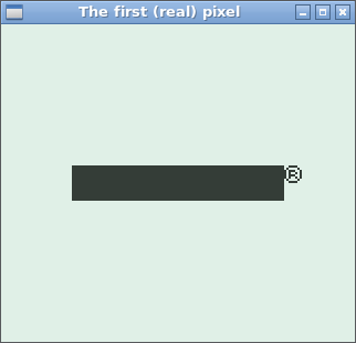
Finally! There are our pixels. Proper color and everything! Now it’d be really neat to see an actual logo instead of that registered-trademark black bar. And also seeing it move, right?
Alas, as this article is once again too long, I’ll save the logo and scrolling bits for the next one. But we’re definitely almost there!
Thank you for reading.
References
- Pan Docs: Graphics
- Pan Docs: VRAM Tile Maps
- Pan Docs: VRAM Tile Data
- The Ultimate Game Boy Talk (the whole Pixel Processing Unit part in particular)
- The coffee-gb source code (I’m so grateful for this)
- Example program: the first real pixel
You can download the example program above and run it anywhere from the command line:
$ go run the-first-real-pixel.go
It expects a dmg-rom.bin file to be present in the same folder.
-
One could argue that anything showing on your screen is technically made of pixels but this is not the kind of pedantry we’re here for. ↩︎
-
Wikipedia says GOO-ee, I love it and I wish I had looked it up sooner. ↩︎
-
Though while researching OpenGL, I’ve stumbled upon absolutely fascinating articles, some of which I could barely understand but nonetheless loved and still learned a few things from. ↩︎
-
It was a mere clone of an existing puzzle game, written in PyQt, and the code is still on Sourceforge! I’m also slightly proud that the game’s website is still there and working, despite a shameful “stay tuned for version 1.0” (there never was one) on the front page. Oh well. ↩︎
-
To be honest, though, my last experience with Qt is about a decade old at this point, maybe I could come up with a custom QWidget to act as a screen of sorts, and I know Qt has sound support so… I may yet give it a try someday. ↩︎
-
Source: pretty much every color picker ever. ↩︎
-
This turned out not to be such a useful design decision because for some reason, most of the SDL bindings in Go use separate
r,g,bandavariables instead of aColorstruct. ↩︎ -
Since we’re emulating an LCD screen, I’d expect 0 to represent an absence of electric current for a given pixel, hence it would look white, then increasing values would get a darker pixel. The slides I borrowed from the Ultimate Game Boy Talk do the opposite, representing black as all zeroes and white as all ones, like you would in RGB. Both are totally valid, thanks to palettes! ↩︎
-
This is an excerpt from
hexdumpstarting at address0x8000. The*means that the following rows are all identical. ↩︎
